
A Clean Anchor Chain?
Okay, so why would you want a clean anchor chain? Two reasons, really. First, if it's muddy, we really don't want all that muck getting in the anchor locker, and second, it's no so much clean, the goal is really to have no salt residue left on the chain.
Chain is zinc galvanized, so it is corrosion resistant, but there is only so much zinc on the steel chain, so the less work that zinc galvanization has to do to protect the underlying steel, the longer it will last!
Manual Cleaning
Up until now, we have been able to use a fresh-water hose and multi-position sprayer set to mist, which I would lock into "On" and then position the sprayer so that it would spray down through our bridle access opening to rinse the chain on the way up.
When you are in sandy anchoring spots, that is pretty much all you need; just enough to get the saltwater off.
Now, there have been times where we anchored in thick mud (the Chesapeake Bay, Maryland, USA and Cocorite, Port of Spain, Trinidad, I'm talking about you!), where the chain is not even visible through the tube of mud surrounding it! In these cases, the chain basically needs a full-force and continuous spray of high pressure water to really get it clean. Fortunately, that is not our normal case.
A Better Way
Since the normal goal is just to rinse off the saltwater, I wanted to add a better way to do this. For one, it's kind of cool to automate things, but also, there are times where it takes some time to position the boat so that the windlass can pull up the anchor chain, without trying to pull the boat forward. When that happens, I usually don't bother to turn off the sprayer, but it is wasting what is basically fresh drinking water.
The Parts
The parts used to make this come together really centered around a few things. Tbe links are for what I used. Adjust quantities and dimensions are needed!
- 6mm black polyurethane drip irrigation tubing (I only needed about 12 feet)
It is easy to work with, cheap, UV-resistant and flows plenty of water - Some plastic hose clamps to hold the drip irrigation tubing in place
There are a couple of ways to go with this, these are not what I used, but would be I were to do it again. - Plastic drip irrigation quick-connect fittings
These make the job go together easily and they are also cheap - Misting Nozzles
These plug into the 1/4" quick-connect fittings and create a fine mist. - Some M3 stainless steel machine screws
These go through the holes in the quick connect fittings to fasten everything securely. - 15mm quick connect PEX fittings (Stem Tee) (Elbow) (NPT Male to Quick Connect)
To tie into the boat's existing plumbing - 15mm quick-connect Shut-off valve
So that the system could be isolated in case a leak springs - 15mm PEX tubing, blue (I ordered 2 ft, but 1 would have been plenty)
A few small segments were also needed to tie into the boat's existing plumbing - A 24V electric solenoid valve (12V Version)
This is powered when the windlass is powered to automatic the spraying. Our boat house battery bank is 24V DC, but there are also 12V versions available. - Brass Adapter - 1/4" NPT Male to 1/2" NPT Female
To make the connection from the 15mm Push-to-Connect fitting to the solenoid - Brass Adapter - 1/4" NPT Female to 6mm Push-to-Connect fitting
To make the connection from the solenoid - Two M5 Stainless steel machine screws
These mount the solenoid to the boat. - Teflon Tape
Used to both provide a leak free seal and also to insulate between dis-similar metals. - Some anti-corrosion jointing compound (Duralac(probably hard to get in the US) and Tef-Gel are both good options)
Use this to protect from bi-metallic corrosion. If you don't already have this (which you should!) - Marine Grade duplex 20-AWG wire (buy locally as you will not need a full spool, we needed 3')
For connection from solenoid to anchor windlass control - 1/4" Split wire loom (we needed 3 feet)
Use this to route and protect the wiring going from the solenoid to the anchor windlass control box. - Inline blade fuse holder (something like the one linked, smaller gauge is better to join to 20 AWG wire) - Adjust based on how exposed this will be for your installation
To be installed just after the connection to power. - 2A blade fuse (should be good for 12V or 24V solenoid valve)
To protect the wiring from shorts - Crimp connections and/or soldering implements
Used to connect to the solenoid wires, fuse holder and connection points in windlass control box. We needed ring terminal connectors for that connection and solders and heat-shrinked everything else.
The Steps To Do This
This is obviously going to vary based on the boat, etc, and it also assumes that fresh water is already close to the anchor. If you only have salt water washdown, don't bother with this solution. The mist is not strong enough to remove mud, and the misting nozzles will quickly clog from the salt.
Water connection
We are lucky because on Mira, there is already fresh water in the storage locker directly starboard of the anchor windlass. That is where the hose spigot is located.
On Mira, the valve to turn off/off water to the spigot is attached to the boat with 15mm quick connect PEX tubing.
Here were the basic steps:
- Turn off the water pumps and de-pressurize the water system
- Disassemble the existing pieces from between the bulkhead and the valve.
- This usually involved pulling back on the release ring and pulling out the tubing.
- Make use of the existing venting hole in the bulkhead to bring pressurized cold water into the windlass/chain locker.
- Use the quick connect fittings and pieces of 15mm PEX to create a location for the on/off valve and solenoid valve in the anchor locker.
- Make the connections to the solenoid with the adapters. Make sure to observe the flow direction cast into the bottom of the solenoid valve and make sure to use Teflon Tape to coat the threads before assembly.
 |
| Added Stem Tee to pass PEX Tube into Anchor Locker |
Solenoid Mounting
We used some long machine screws installed through the starboard bulkhead of the anchor locker to mount the solenoid after getting all of the PEX measured, cut and fitted together.
Getting the location just right is not easy. We photo-copied the bottom of the solenoid valve to figure out the mounting hole spacing and then drilled the holes a little larger than needed to so they would be able to start without forcing or potentially cross-threading.
The valve is brass, so adding anti-corrosion jointing compound to the screw threads is very important!
 |
| Shut-off valve and Solenoid Valve in Anchor Locker |
Mounting the misters
I attached the misters to the quick connect fittings (all tees except an elbow on the end). I had the chain off the boat to make access easier, but I think it would have been better to have the chain in to make placement of the misters easier/more accurate.
I placed the plastic fittings where I wanted the misters located and then marked through the holes to know where to drill.
I decided to drill and then tap the holes for the M3 screws so they would be threaded into the aluminum longeron on Mira. This was an absolute pain and difficult to do without breaking taps because the sizes are so small. If I were to do it again (and I might change it anyways), I would drill clearance holes, then use longer M3 (or 1/8" if you have to use imperial sizes) machine screws and just use a nylon insert lock nut on the back side.
With either approach, just make sure you don't have stainless against Aluminum without jointing compound or the aluminum will corrode in no time. You may even want to use some nylon washers to insulate the heads and nuts from the aluminum, but at the least coat the threads with compound.
 |
| Misting sprayers at anchor resting position |
 |
| Misting sprayer near anchor resting position |
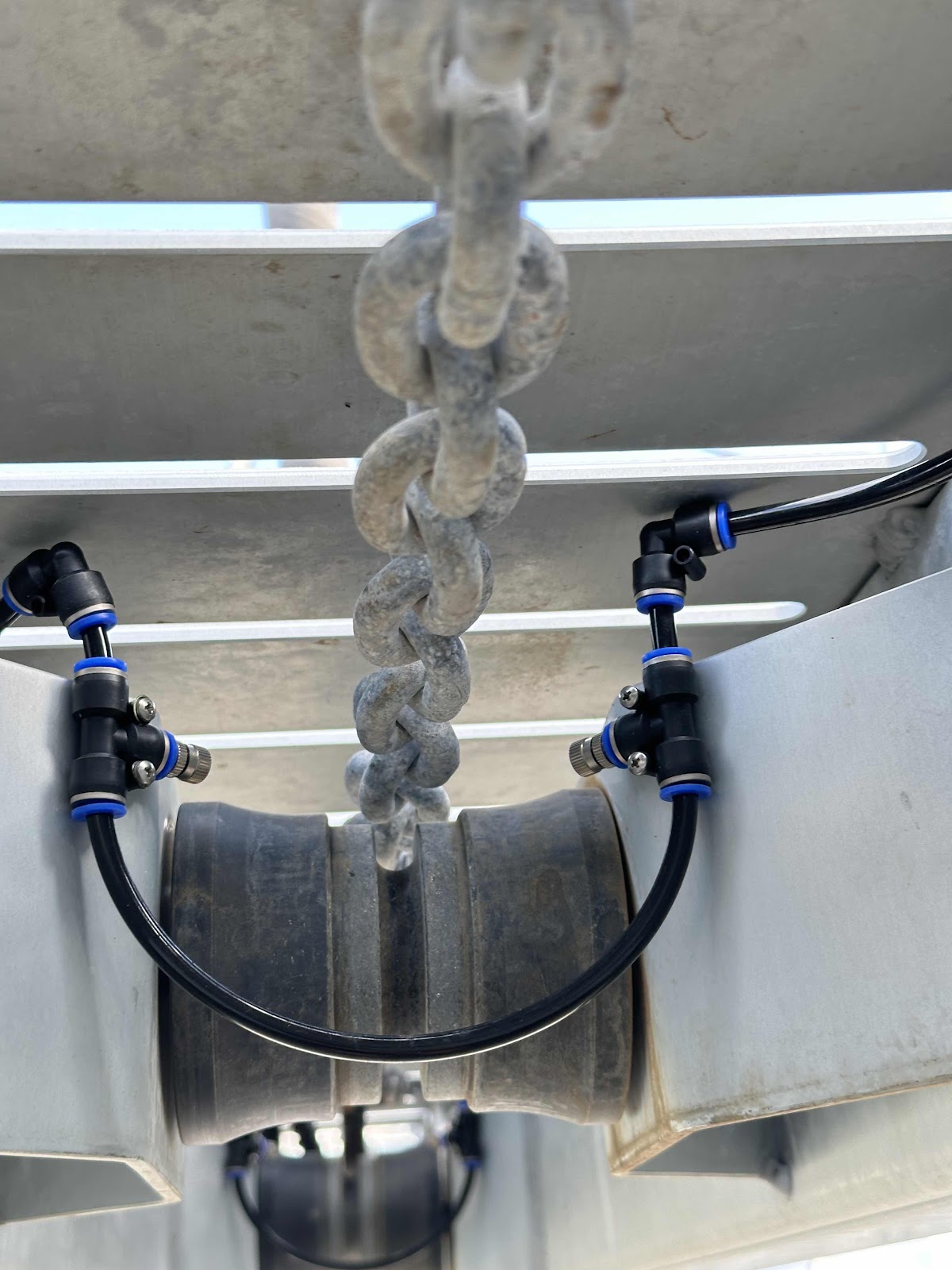 |
| Misting sprayers near aft anchor chain roller |
Plumbing in the Misters
The 6mm tubing is very flexible and it's possible to bend it in about a 30mm radius instead of using an elbow, but that kit linked above includes a good number of elbows and that makes the installation easier and also requires fewer hose mounting clips, so that's what I did.
Figure out how you want the tubing mounting (using the adhesive backed mounting clamps) and get the lengths exactly as you want them. You will have plenty of extra tubing, so don't be afraid to re-cut if you are not happy with the length. MAKE SURE they are fully seated in the quick-connect fittings, it is very easy for them to not be in all the way, which means they will let loose under pressure.
After you are happy with the layout, thoroughly clean the surface to which the hose clamps will mount and then clip the clamp onto the hose and press firmly in place for about 15 seconds.
Plumbing to the Solenoid
The 6mm tubing now exists under the longeron and must get to the quick connect fitting on the outlet of the solenoid valve. This means drilling a hole through the hull. For now, we simply have a 6mm hole drilled through the hull to get the tube inside. It is a very tight fit so water ingress is all but impossible. We also have a foam-core boat, so it is also not as big a concern. If you have a wood cored boat, it is imperative to drill the hole larger (6.5mm) and then coat the inside of the hole with an epoxy (such as a hull primer). When dry, insert the tubing and then seal it with sealant for good measure.
We taper-cut a longer piece of 6mm and forced it into the opening and it is a very, very tight fit. Eventually (and when I can find the hardware), we will replace this with two 6mm ID grommets, one mounted from the outside, one from the inside, both epoxied in and sealing the interior foam core.
We used an elbow on the outside and inside of the hull to keep the tubing tidy and less likely to get snagged by something.
Figure out your routing and install more adhesive hose clamps along the inside to route the line.
Cut a nice clean edge at the right length and then insert into the outlet of the solenoid.
 |
| Attachment of 6mm tubing and entry into hull |
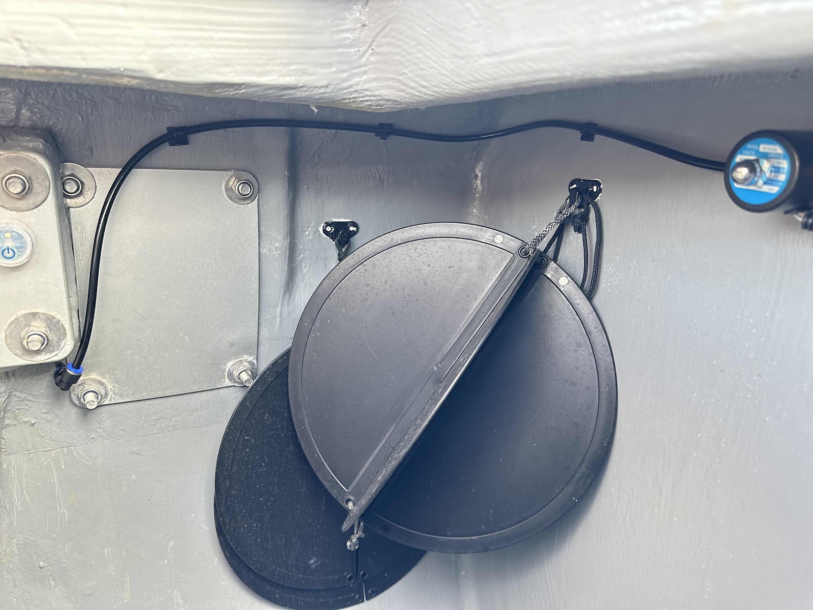 |
| Internal routing of 6mm tubing to solenoid valve |
Wiring from the Solenoid to the Windlass Controller
This is obviously going to vary by installation.
We have a Lofrans Tigress 1500W, 24V windlass. It has a control box mounting in the area behind the anchor locker (where out glassed-in diesel tanks are located).
I soldered in a length of duplex wire to the pair of wires coming from the solenoid (the connections on this solenoid are not polarized, as it just powers an electromagnetic coil and pulls up on a ferrous element).
This was then placed into split wire loom and routed into one of the wire glands going into the windlass control box.
Once inside the box, the black wire was terminated to the ground connection in the control box. I cut and stripped the wire and then crimped on a heat-shrinkable ring-terminal. Our control box contains a large fusible link in the ground path. I attached the ground lug to the windlass side of the fusible link.
The red lead was connected via butt splice crimp connector to the fuse holder (after trimming the lead length of the fuse holder down).
On the other side of the fuse holder, I crimped a ring terminal that would attach to the output of the windlass control solenoid.
 |
| Loomed cable routing from anchor locker to windlass control box |
Making the Actual Connections
Our windlass has three terminals; a ground, a upward rotation terminal and a downward rotation terminal. The solenoid for the windlass takes switch input from the deck-mounted buttons and the helm mounted button/chain counter and then based on those inputs activates the solenoid (relay) to send 24V to either the up or down input on the windlass. The ground terminal is always connected to vessel ground.
I believe that there are two sets of windings in this type of windlass, one for clockwise rotation and another for anti-clockwise rotation. If you have a two-wire windlass, you have one winding in the motor and a more complicated solenoid is required to reverse the polarity between wanting to go up or down with the chain.
The Easier and Safer Connection
The easier and safer answer for both is to have the solenoid activate if the chain is going up or down. Does this waste water: yes, but a very small amount, since misters really don't dispense that much volume of water.
The reason this is the safer connection, is because the solenoid valve is powered by the windlass solenoid. There is an extra 1A (less, really) of power consumption for the solenoid valve on what is on the order of 100A going to the windlass.
The connection is easier, because you don't have to figure out how wires from deck mounted buttons are powered. You just connect the solenoid valve to the wires going to the windlass and you are all set.
But on a Three Wire Windlass, There Is An Up Wire?!
You may be thinking, I already have a dedicated "Up" terminal to which I can connect, so I can just connect to that wire and it will only run when going up.
I thought that as first too, however, the two windings that exist within the windlass still exist next to each other. An electric motor and an electric dynamo/(generator) are basically the same thing. In the motor, an electric current is being applied to windings, and the magnetic flux is causing the rotor of that motor to spin. In a dynamo, the rotor is being spun by and outside force and the magnetic flux generated by this is induced into the windings and generates power.
So, when the down winding is being power to create motive force (as a motor, moving the chain down), the other up winding is acting as the winding of a dynamo and creating voltage! Pretty neat and in this case, pretty annoying!
There Has to Be a Solution For This!
There is a solution for this, actually a couple, and they vary from terrible to possible.
Option 1: Use a diode
Insert a diode between the windlass solenoid UP output and the windlass Up input and then connect the solenoid valve power between the windlass solenoid and diode.
This prevents power from coming FROM the windlass up terminal when the down motor wincing is being powered. The only way the solenoid valve can be powered is from power coming through the windlass solenoid, not from the motor acting as a dynamo.
This is a terrible solution because of the size that the diode would have to be. (Read, huge) Also, it reduces the voltage getting to the windlass motors, which is harder on the motor and will reduce its life. It also will cause the diode to create heat. This can be ruled out as a stupid/terrible option.
Option 2: Power the valve from the Up Switch
Powering the solenoid valve directly from the "UP" switch(es) is an option; it is basically powering the solenoid from the input side of the windlass solenoid, but it carries some risks. It will takes some research to make sure that the exact wiring is understood (what voltage, is it fused, can the switch(es) handle the added current?) If it is already fused, it may be possible to remove the added fuse, but there is no harm in keeping it. If the voltage is not the same, that would be weird, but possible and then the solenoid valve may need to be different. The big one is "can the switch(es) handle the added current (about 1A from my measurements) of running the solenoid valve in addition to the windlass solenoid.
The biggest challenge is probably going to be finding out what the switches (deck mounted and control panel/chain counter) are rated for. While a stand-alone, general purpose switch you buy will certainly have these ratings, the ratings for a switch part of a "windlass-system" likely will not.
You may be able to make sure educated guesses, for example, I can look at the contact area for the deck mounted switches and see that they can handle a lot of current, probably 10A, but for the ones in the controller at the helm, that is a lot harder, especially without taking the controller apart. What is switching the current? A relay? A output from a microcontroller (unlikely)? A FET (Field Effect Transistor)?
If you can find the switch ratings, you will then have to find out how much current the windlass solenoid inputs take and see if there is another 1A of headroom so that the solenoid valve can be powered.
Or you can just try it and risk damaging your boat, the controller or the switches.
So, this option is possible, but takes either a good amount of research or some risk.
Option 3: Power the valve from a small relay connected to the Up Switch.
This is like option 2, except we are reducing the added power going through the Up switch(es) by only having to power the coil of a relay.
Technically, the same research as above should be done, however in practice, the amount of current required to power the relay coil will be around 0.05A. It is incredibly likely that at least this amount of headroom exists.
The connections are not complicated, but the physical space of the relay, while not large, must be accommodated. In short, the coil is connected to the UP switch input of the windlass solenoid and to the ground. The normally open switch connections on the relay are connected to 24V, after the 2A fuse and then to the solenoid valve power.
This is the best option, thought the most complicated.
Summary of Options
Option 1 is terrible and should not be considered.
Option 2 could be an easy and safe method, but will take some research of values that may not be findable.
Option 3 is the best option if the current ratings and usage values can't be found. The risk of switching too much current through the switches is not zero, but wince the amount of power for a relay is so small, the risk is exceptionally low.
Summary of the Project
The project was not overly complicated, but that was only because we were on the hard to do it. Trying to do this while standing in a dinghy, etc. would have been really terrible. We have still yet to launch so we have only been able to test the system by lowering and raising the anchor in the yard.
I'll try to post an update after we have actually used this for real and also report back how the system has held up.
Updates!
Research into ratings
I would really like to have the solenoid valve and therefore the sprayers only operate when the anchor is being raised. In order to do that I need to implement Option 2 or 3 above.
Here is what I need and what I've found:
- Lofrans Footswitch current rating: 4A - Found under Section 2 of the Installation and User's Manaul
- Lofrans IRIS 2 helm controller and chain counter Up/Down output rating: Not specified
- Lofrans Control Box (1500W, 24V) current draw: Not specified
Given that two of the three values are not given, I've reached out to Lofrans Tech Support to see if I can get them. I could measure the input current on the Control Box, but without knowing the actual output rating for the IRIS 2, it is of little value.
No comments:
Post a Comment